Donn Stewart
13917 Deviar Dr
Centreville, VA 20120
dstew@cpuville.com
13917 Deviar Dr
Centreville, VA 20120
dstew@cpuville.com
I have wanted to make a new processor for some time, and I wanted to try using an FPGA. I found a Terasic DE-10 Lite development board on eBay, and decided to try this project.
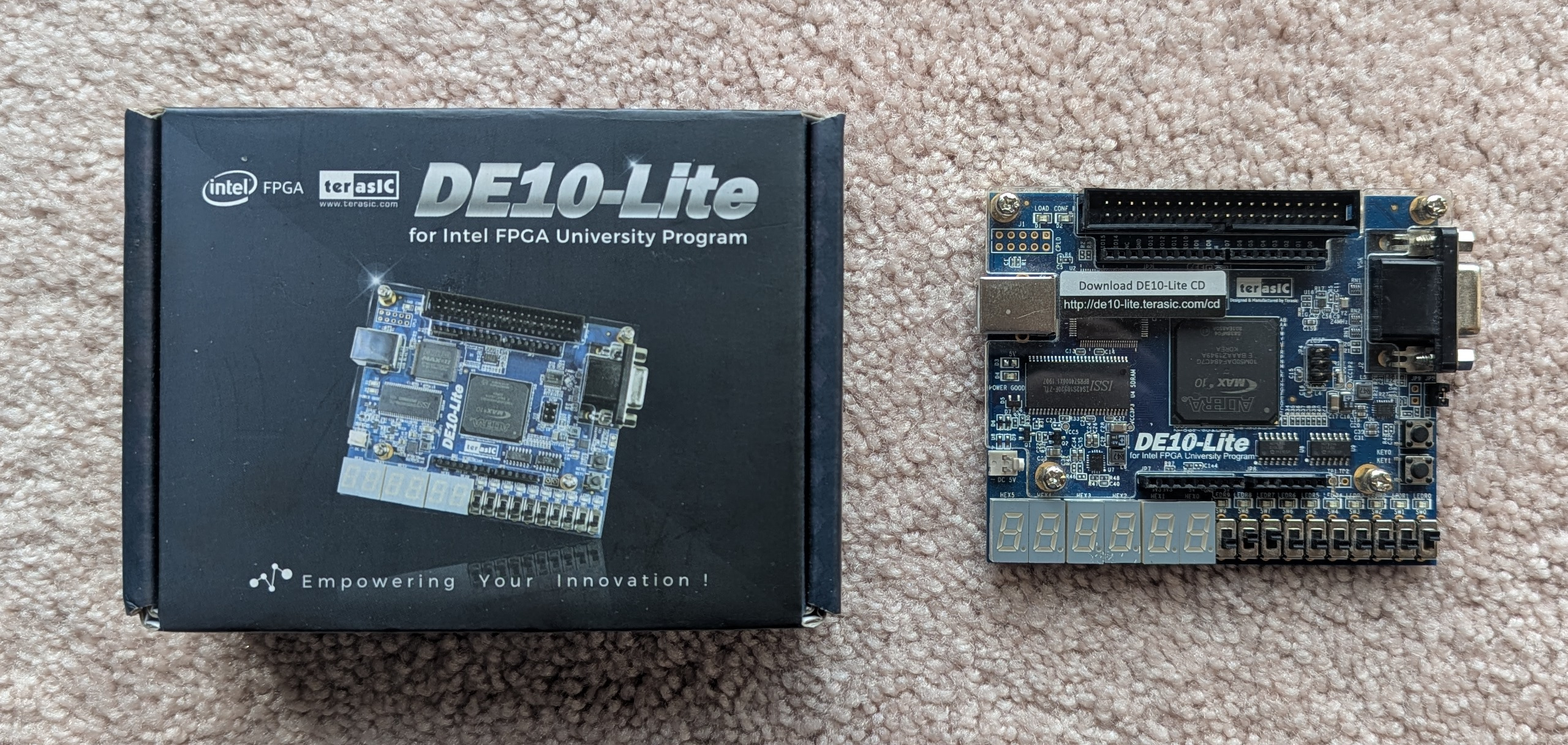
See the project page for all the details.
It's been a while since I posted anything here, but I am still active with the kit sales. And I wanted to post this information on how to overclock the Single-board computer.
The clock speed used in a computer system depends on how fast the hardware can respond to signals. In the Single-board computer, the limiting hardware has been the Z80 CPU and the ROM. Originally, I was using ROM that had a 450 ns delay between when the chip select, address, and read signals were received by the ROM and when the data was ready to be read. Also, The Z80s I supply are rated at 2.5 MHz. With the requirement of the clock circuit to provide a BAUD rate clock to the UART, the 1.8432 MHz system clock was decided on.
However, more recently I have been using ROMs that have a 250 ns, or even 125 ns delay. And even though the Z80 is rated at 2.5 MHz, there are many reports that it can be clocked faster. Experiments by two customers have confirmed that the Single-board Z80 computer kit can be clocked faster by two different methods.
The first method was communicated to me by Tom Lovie. He simply replaced the 1.8432 MHz oscillator on the computer board with a 3.6864 MHz oscillator. Since the computer board oscillator drives both the Z80 CPU and the serial port UART, this resulted in a system with a faster Z80 and a serial port BAUD rate of 19.2 KHz. He had purchased a Z80A processor (rated for 4 MHz) but stated that the regular Z80 (rated for 2.5 MHz) worked fine at this higher clock speed.
The other method is to use a higher-speed external CPU clock. This is easy to do if you have a bus display, since that board has an oscillator on it that is used exclusively as the CPU clock. Customer Jason OKeefe replaced the 1.8432 MHz bus display oscillator with a 6 MHz one, and replaced the Z80 with a Z80B rated at 6 MHz. He reported that the system worked fine with a noticeable improvement in performance of the Sargon chess program under CP/M.
Two customers recently contacted me about a problem they were having with the bus display for the Single-board Z80 computer. The slow clock was not cycling, and the U3 74LS04 IC was getting extremely hot. I checked this myself and confirmed the behavior, on a bus display PCB and on the slow clock circuit on a breadboard. The problem is related to the 74LS04 IC itself. The ICs that get hot and fail to cycle all have an odd logo, that the technical support supervisor at my parts supplier thought might be a poor copy of a Texas Instruments logo. Here are the photos:
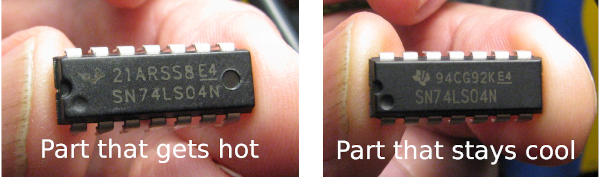
I could not find this logo on any of the lists of known IC makers. The ICs came from China, and I thought perhaps the logo was not a poor copy of the state of Texas, but an outline of the map of China. If anyone knows which company made this IC I would like to know.
Interestingly, the IC tests fine as an inverter in the usual test systems, which in my case is a TL866CS programmer in IC test mode. It also works fine in kit circuits that use it as a signal inverter, like in position U1 on the Single-board Z80 computer. However, there is something significantly different in how this IC reacts to timed events, like the oscillator circuit. This same IC brand is the source of the problems I was having with the 8-bit processor that related to the timing of a delay circuit. See the News and Issues article of November 12, 2019, "Processor problem".
Is this IC a counterfeit Texas Instrument part? That is hard to say, since the odd logo in the chip, while resembling a TI logo, would be a pretty poor copy if this is what the maker intended. The writing on the surface is laser-etched and does not come off with acetone, a test that reveals many counterfeits. And, the IC does work as an inverter. So perhaps it is a 74LS04 that is made with different characteristics than the TI parts, or other genuine US-manufacturer parts that work in my oscillator circuit. I contacted TI, and they said the only way to know if a part with a TI logo is genuine is to follow the supply chain back to an authorized TI distributor. Since the 74LS04 part is obsolete, TI does not make it any more, unless there is a big order for them, then they might make a batch. But that would be thousands of parts. So I am left with buying from whoever has them, and I can't be sure if they will work until I test them in the oscillator circuit. And, unfortunately, these 74LS04s with the odd logo seem to have saturated the market. I could not find anyone with 74LS04s for sale at a reasonable price that at least look like genuine TI (or other manufacturer) parts. There was one TI-authorized distributor of obsolete parts that would sell me genuine TI new old stock 74LS04s -- for $10.00 each!
Fortunately there is a work-around. If you have the problem described here, that your bus display slow clock won't work and the IC gets hot, you can swap the bad IC for the U1 IC in the Single-board computer (if that IC is not one of the odd logo ICs). Also, I have tested 74HCT04 ICs in all the postions of the Single-board Z80 computer, bus display, and the 8-bit processor system, and they work fine. So I may just substitute 74HCT04s for the hard-to-get 74LS04s in my kits from now on. I will include a note with the kits that mentions the substitution.
I just became aware that the v.15 EPROM (see the News and Issues item of May 17, 2020) was unable to load the small-system CP/M operating system that uses cpm_loader.bin as the loading program. The v.15 EPROM will load large-system CP/M, which uses cpm_loader3.bin. The cause was a small bit of code in v.15 that I accidentally left in after some editing. The problem I was dealing with was that the disk_read ROM routine had a different address in the v.8 and v.15 ROMs. The cpm loaders use this ROM routine to load CP/M. My first attempt at solving the problem was to put some code in the v.15 ROM that would "patch" the address in the cpm loader after it had been placed in RAM when executing the cpm monitor command. Later I decided to just move the v.15 disk_read ROM routine so it would have the same address in the v.8 and v.15 ROMs. I made some other changes in the v.15 ROM, but I forgot to take out the original patching code.
When I started shipping v.15 ROMs I was testing them with a large-system CP/M that was using cpm_loader3.bin. With that cpm loader, the patch would put a byte in a non-coding area of RAM, so it had no effect, and I thought the v.15s were working fine. But thanks to the expert help of a recent customer (thanks Andreas!) we saw that the patch was active in changing the disk_read call address in the loader for the small-system CP/M, and because of other changes I had made to the v.15 code, the result was that the cpm loader was calling a ROM routine that put a newline on the screen instead of reading the disk. So instead of loading CP/M it was putting out 50 newlines!
Anyway, all fixed now, I just removed the offending patch code from the v.15. If you have an affected v.15 ROM, there are several options for you. You may return your v.15 EPROM to me and I will re-program it. If you have the ability to erase and program your own, the website now has the updated v.15 ROM code on the Code page, and you can do it yourself. The other option is to install a large-system CP/M that uses the cmp_loader3.bin program. See the "CP/M System Update" boxed advisory in the Single-board Z80 computer instruction manual, or go to the CP/M code update section of the CP/M Code page. If you have any questions, please contact me.
Over the past year a number of customers have had trouble getting their Z80 computers to work due to inadequate power supplies. The key issue seems to be the amount of capacitance in the power supply output. Computers such as the single-board Z80 computer have rapidly varying current requirements while running due to the continual changes in the number of logic gates that open and close as it goes through its cycles. This rapid switching in gate currents can lead to voltage drops if the power supply cannot keep up. These drops in voltage, even if brief, can bring the computer to a halt.
Over the years I have not paid a lot of attention to the power supplies used in my projects. I have generally used "PC-quality" power supplies, often pulled from old PCs or laptops. These supplies have large output capacitors and good voltage regulation. However, when I released my kits "into the wild" they have been connected to all sorts of power supplies, some good, some not so good. The very worst are 99-cent "wall warts" that have such poor regulation that voltage spikes at power-up have damaged components. But usually the problem is a power supply with good regulation but inadequate output capacitance. Often these are power supplies that were designed for recharging batteries or running non-computer electronics such as clocks or sound systems. These applications do not require the kind of output capacitance needed for computers. A USB charger is an example of a well-regulated power supply that will usually not work with the Z80 computer due to inadequate output capacitance.
The solution is simple: more output capacitance. Two customers fixed their problem by connecting a 100 uF capacitor across the voltage input of the Z80 board. Others fixed it by using a PC-quality power supply. These can be old ATX power supplies pulled from PCs, or wall warts that have been designed for computer equipment, like routers. I sell a power supply that works well.
This explanation may be simplistic, and the real issues more complex. But the bottom line is this: If you built your computer and it doesn't work, the power supply may be the problem. If you need help getting your CPUville computer to run, contact me. If we can't figure it out, you can send your kit to me, and I will check it out for you, no charge.
I have expanded the Z80 computer with the video display (see the April 30 post below) into a full standalone system by adding a PS-2 keyboard interface and a system monitor in ROM. The ROM also contains a version of the Tiny BASIC interpreter. The computer now no longer needs the serial port for console input and output. The serial port is used only for loading programs into the computer. For details, see the Standalone Z80 computer project page.
This new ROM combines some features of the v.7 ROM that came with the Original kit with all the features of the v.8 ROM that comes with the Single-board kit. Like the v.7 ROM, at power-on or reset the computer takes an address from the input port switches on the display board and jumps to it. The ROM has three short demo programs from the v.7 ROM; the port reflector, the simple counter, and the count-to-a-million programs. It also has a full system monitor, with the disk access routines of the v.8 ROM, including the ability to start CP/M if you have it installed. This new ROM makes it easy to use the full set of features of the Single-board computer with the bus display, to show on the slow or single-step clocks the full operation of the Z80, and also to run CP/M.
A pre-programmed v.15 ROM is available as an accessory. The code for this ROM is also on the Z80 Code page, and can be downloaded for those who can program their own EPROMs. Note that the addresses for the routines in the v.15 ROM are different than they were in the v.7 and v.8 ROMs. Refer to the v.15 ROM list file on the Code page to find the addresses. If you have just bought a Single-board computer, and want to install CP/M, please install it using the v.8 ROM that comes with the computer, because the installation programs depend on v.8 ROM routines, and these routines have different addresses in the v.15 ROM. However, once installed, CP/M works the same way with the v.15 and v.8 ROMs.
Many customers and fellow hobbyists have asked if I had a video display for the CPUville computers, so that the computers could be used as "stand-alone" systems without the need to connect to a PC to use the PC keyboard and display. I have been working on a video display, and I am reporting my progress here.
The display produces a monochrome composite video output with a resolution of 320 dots by 240 lines. I have integrated the display into a simple Z80-based computer system where it acts as a memory-mapped display. It occupies 9600 bytes of RAM. The computer uses the serial interface from my Original kit, and a modified version of the v.8 ROM monitor, so I can load programs and images from the PC for testing in the video system. With a Z80 B processor running at an overclocked 8 MHz, the display updates quickly. Here is a demo video:
I will code some simple video games and see if this is something I will continue to develop. Next I will add a keyboard interface to the system to allow the computer to operate free of a connection to a PC.
If you are interesed in details of this project, please email me. I will eventually put up a project page on the website.
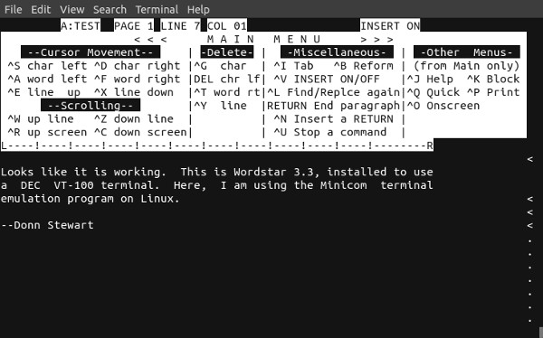
A comment from a YouTube viewer triggered some "computer archeaology" to see if I could get MicroPro's WordStar word processor program running under CP/M on the single-board Z80 computer. After some false starts I was able to get WordStar 3.3 working. It works with the terminal emulators Realterm and Putty on Windows, and with Minicom and Picocom on Linux.
I found the program in The WordStar Collection archive at Retroarchive.org. I downloaded the WS330.zip file that contained WordStar 3.3. After extracting the archive on my PC, I transferred the files WSINSTALL.COM, WSMSGS.OVR, WSOVLY1.OVR, WSU.COM, and WS.INS to the CP/M disk on the Z80 computer. Note that WS.INS is too large to transfer using the monitor -- CP/M SAVE method, you will need to use PCGET.
Once the files were transferred, I ran INSTALL under CP/M. It asks a series of questions for setting up WordStar. I chose the DEC VT-100 terminal. For a printer, I chose half-linefeed, no protocol, and CP/M list device. There is of course no printer port on the Z80 computer, but you have to choose something to get through the installation processes. After making these choices, the INSTALL program modifies the WSU.COM file to produce a WS.COM file. To run, type WS at the CP/M prompt.
Since I began selling the Single-board Z80 kit sales of the Original Z80 kit have fallen off dramatically. This was expected. I just shipped the last Original kit I had, with the last circuit board. So now I am faced with a decision. Should I order another shipment of Original kit circuit boards? One order is many hundreds of dollars, so if I cannot sell them it would not be wise to do so. But there is still a small demand for the Original kit. So here are some of the options I am thinking about.
1. Just reorder. I only sold 10 Original kits in the past year, so if I order 50 boards to keep the per-board price low, it will take 5 years to sell them at this rate. But this is an option.
2. Make an updated version of the Original kit. The Original kit circuit board was the first printed circuit board I designed, and it has some obvious flaws. The printing on the front is not optimal. There are many improvements that could be made. The resistor network footprints were put in backward, so you have to put pin 1 at the pin 10 position. I could do a simple "facelift" and improve the markings and put the resistor network footprints in properly. But there is another possibility.
3. Make a completely new "Original" kit. In addition to the appearance and the resistor network problem there are other things about the Original kit system that could be improved. The DIP sockets that connect the board to the accessory boards get loose over time. It would be better to use a standard header. The Original kit had fully buffered address and data buses. I think these buffers are not necessary. If I remove these buffers, the board could be made smaller, and save a little on board cost. Also, the Original board did not have all the Z80 signals brought out to the accessory board connector. This limits what kinds of accessory boards one can make and use. In particular, if one wanted to make a memory-mapped display, one would like to have the Z80 WAIT or direct-memory access controls available.
I have not decided what to do. For now I have suspended sales of the Original Z80 computer kit. The accessory kits are still available. I am looking for feedback from hobbyists and students out there to steer me in a particular direction. The hobbyist in me wants to do the completely new kit. What do you think? If I get commitments to buy a particular kit from 10 or more people that will help me to go ahead and spend the money needed to work up a new kit. I look forward to hearing from you!
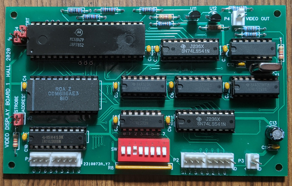
Fellow builder Travis Hall has created a simple video display board for use with vintage computers and other equipment. He sent me one for testing. It is based on the MC6847 video display generator, which was used in the TRS-80 and other early PCs. The board takes parallel input and displays upper-case alphanumerics, 32 characters by 16 lines, with composite video output. It also has two graphics modes.
The board is very nicely laid out, with all through-hole components, and labeled fully. I used the Z80 single-board computer to test it. Here is my setup:
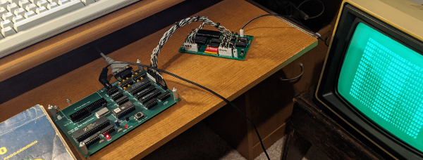
Travis provided a custom cable that connects the lower 9 bits of the address bus (8 bits for a port address, one to reset the display), the data bus, and power from the Z80 computer to the video board. The board has two methods of receiving data. One is simple strobe, the other is addressed. Jumpers are used to select the data transfer mode, and to select text or graphics. I used the address mode for data transfer, and assigned the board I/O port 4 using the DIP switches on the board (note least-significant bit is on the left). I attached the display board composite video output to an old monochrome monitor from the Apple ][ era.
The board worked beautifully. The image is rock-steady, and the upper-case font brought back memories from the 8-bit PC era. The graphics mode displays 4- or 6- pixel blocks, and worked perfectly, once I understood that 6-bit graphics needed both graphics jumpers on.
Bottom line, this is a nice, simple display option for vintage computers or other simple projects for which one might want a display. The parallel inputs are convenient for use with minimal hardware. Travis has not decided if he will offer this as a kit, but he will share the information with you:

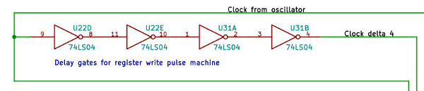
I assembled a processor kit for a customer, but during testing it did not work. I traced the problem to the 4-inverter clock delay circuit shown above. This circuit is meant to create a timing offset between the upgoing edge of the master reset signal to the register write pulse machine, and the upgoing edge of the clock pulse to the same register. These two edges need to be at least 10 ns apart for the register to produce the register write pulses sent by the control board to the rest of the processor.
I used this scheme in my original processor project, where it worked well. So I carried it over to the 8-bit processor project and kit. However, it has a weakness. If the inverters in this chain are very fast, the propagation delay will be less than the required 10 ns, and the processor won't work. I found that some of the 74LS04 ICs I had recently purchased had this "flaw" -- they were too fast! When I used 74LS04 ICs from other manufacturers, the processor worked properly.
I will only ship tested 74LS04 ICs with the 8-bit processor control board kit. The fast ICs do not affect any other parts of the processor, or the Z80 kit. If you are using the 8-bit processor kit circuit boards and your own parts to build the processor, be aware of this issue. If the control board is not generating register write pulses you may have this problem. Using 74LS04 ICs of other manufacturers will probably solve the problem. Please contact me if you have any questions about this.
The lesson is not to depend too much on propagation delays for proper functioning of your processor. If I was to do it again, I would probably use a one-shot circuit to provide the master reset signal to the register write pulse machine, and not rely on the propagation delay of a chain of inverters.
I have had to sharply increase the price of two of the kits. These are the serial interface kit for the original Z80 computer, and the single-board Z80 computer kit. Other kits have seen more modest price increases. The cause of these price increases is due to the price of components. Some components for these kits are no longer manufactured, and the falling supply is making prices high. One component, the 8251A UART used in the serial interface of the kits, has gone from about $3.50 to now almost $10.00 over the past year. It is possible I can find this component for less by using vendors outside the USA, and I may be forced to do this in the next six months or so if prices stay high.
In an effort to keep the hobbyist world supplied with kits at affordable prices, I am offering custom kits. If you have some of the components of these kits already, let me know, and I can put together a kit for you that has only the components you do not have. So, if you have an 8251A UART in your parts box, I can reduce the price of the single-board Z80 computer kit by about $10, and send you a kit that has everything but the UART. I will do this for other parts as well. Let me know what parts you already have, and I will give you a quote for your custom kit.
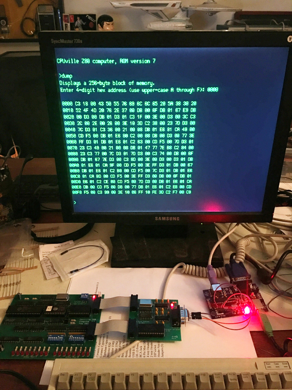
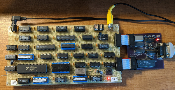
Fellow hobbysits Blake Bartosh and Kent Berglund have built a simple VT100-style terminal kit and got it working with the CPUville Z80 computers. The VT100 kit was developed by Geoff Graham. The terminal kit provides a serial interface to connect to the Z80 computer, a PS-2 style keyboard interface and a VGA video output. This allows you to use the Z80 computers without connecting to a PC. The photo above shows the original CPUville Z80 kit with the serial interface connected to the terminal kit (the board on the far right) producing a text output on the monitor.
The VT100 kit uses a 32-bit PIC microcontroller for producing the display, the keyboard interface, and the serial interface. It also has a built-in menu for configuring the display and the serial interface:
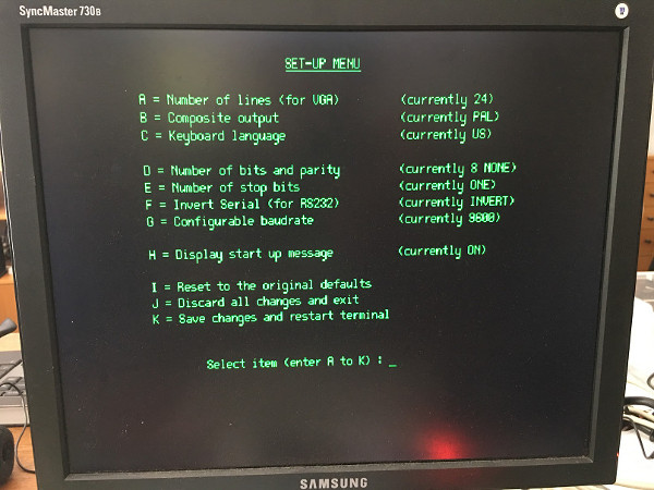
The kit can be connected to serial TTL-level or RS232-level signals without modification. However, the VT100 kit serial interface has only the transmitted and received data connections -- it does not put out the RTS signal that the Z80 computer UART needs to transmit data. However, this is easily overcome by connecting the Z80 serial interface DB9 connector pins 7 and 8 together. The terminal kit GND connects to the Z80 DB9 GND pin 5, the TxD to the DB9 pin 3, and the RxD to the DB9 pin 2. Once connected, the terminal's setup menu can be used to configure the interface, with the settings shown in the photo above. In particular, note that setting F "Invert Serial" is On. This is needed because RS-232 data signals, such as those produced by the Z80 serial port, have inverted bit sense. That is, a "1" is low voltage, and a "0" is high. If you connect directly to the terminal board, without using a second RS-232 transciever on the terminal board, the signals need to be inverted, and this menu selection does that.
The terminal kit can be purchased at Tindie.com for $48.00.
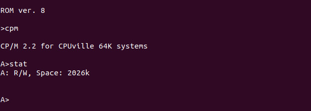
The first CP/M CBIOS I developed stuck close to the original four-disk, 8-inch 250K floppy configuration. However, some users found this quite limiting. I re-wrote the CBIOS to re-define the CP/M disk system as four disks of 2 megabytes each. This required new format, putsys, and cpm loader programs. The installation method is the same as the original system explained in the instruction manuals, but some of the file sizes have changed. If you use the new format program, it now takes about 11 minutes to run, but gives some feedback on the terminal that it is running. I also changed how CP/M maps its sectors onto the hard disk, so it is much more efficient using the hard disk. The original CP/M system needed a miniumum 256 megabyte disk, but this new system, despite the larger CP/M disks, can be installed in a 35 megabyte disk space. I also put in a CP/M cold-start greeting message. To get the new files, go to the CP/M code page.
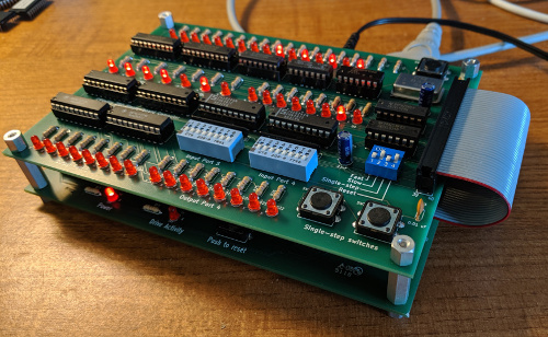
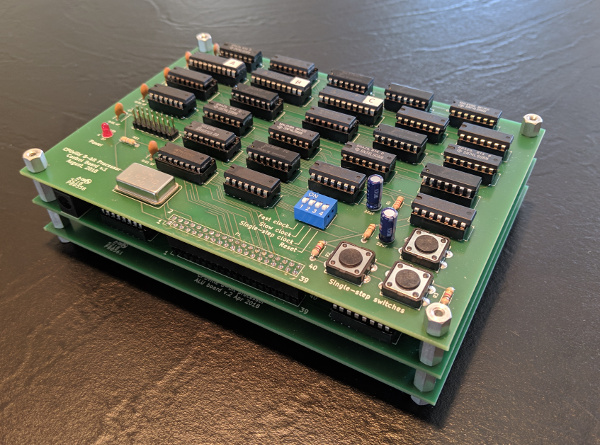
This kit provides a bus display, slow clock, single-step clock, and simple input-output ports for the Single-board Z80 computer. This allows you to explore the workings of the Single-board computer in detail, as you could with the Original Z80 computer and its bus display. For more details, visit the Single-board bus display kit details page. Here is a link to a demo video.
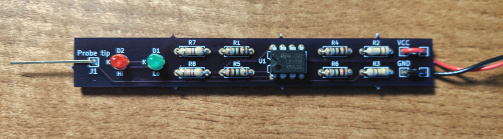
As noted below in the item from November 13, 2018, the original logic probe kit had some difficulties resulting from using op-amps. Op-amps are not ideal for this application since they have a somewhat linear response to input voltage differences, and what is wanted is a more binary, rail-to-rail transition. Comparators are more suited to this. The new logic probe design uses the same voltage dividers as the original logic probe, but now with comparators there is a more reliable detection of high and low levels, and cycling. One difference is the need for pull-up resistors on the comparator outputs since their output transistors are open-collector. For the schematic, and more details, check out the new logic probe instruction manual. Also, the price has been lowered to $5.00 for the kit.
Even more good news. The 8-bit processor kit is ready for sale. This kit is an 8-bit, general purpose, accumulator-memory type computer processor implemented with TTL (transistor-transistor logic) integrated circuits. For a full description, look at the 8-bit processor instruction manual. Please contact me if you have any questions about this kit. It will be a challenge to build, but I will help you as much as I can.
More good news. The Z80 Single-board, CP/M-capable computer kit is now ready for sale. Here is a video comparing the original Z80 computer and the new single-board computer:
This computer doubles as a system board for coming CPUville 8-bit processor kit.
Finally some good news. I have finished making a register display for the 8-bit processor. Here is the demo video:
I intend to offer this as an accessory to the 8-bit processor kit when I put it up for sale early in 2019.
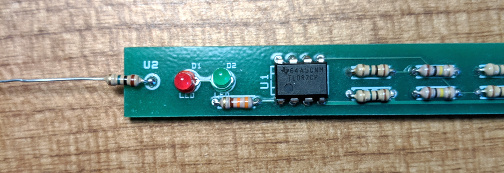
I assembled some logic probe kits recently, and when I tested the finished kits I was surprised to find that they did not detect a low signal reliably. There was a little flicker of the green LED but it would not stay on. After breadboarding the circuit and doing some experiments, it seems that some op amp ICs from some manufacturers are not behaving like the others. In particular, when the non-inverting voltage is close to the V- input to the op-amp, which is ground in the logic probe circuit, some op amps fail. That is, when the inverting voltage is 2.5 and non-inverting is 0.1, the output voltage of the mis-behaving op amp is +4.58 even though the voltage difference is 0.1 - 2.5 = -2.4. The output voltage should drop, but it does not, and the circuit does not work. If I change the voltage divider by putting a 1 meg resistor on the probe input, so that inverting is 2.5 and non-inverting is now 1.4, the voltage difference is 1.4 - 2.5 = -1.1, which is smaller, but now the output voltage drops to 1.35, and the circuit works. Strange.
If you have a mis-behaving logic probe, let me know. There is a simple work-around, which is simply replacing the plain probe tip with a 1 meg resistor, like this:
I am changing the logic probe circuit board to incorporate this 1 meg resistor in series with the probe tip, and we should have no more problems.
Older News and Issues items moved here.