13917 Deviar Dr
Centreville, VA 20120
dstew@cpuville.com


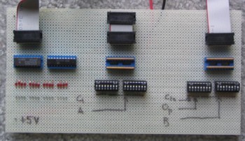
Although not a part of the finished computer, this tester board allowed me to be sure that the ALU, control and memory-I/O boards were working before I assembled them into the computer. It is merely DIP switches for bit input to the two connectors on the right, and an LED display for output from the connector on the left. A jumper can connect the center switch bank to the left connector when a bidirectional bus is being tested or used. The tester board also served as the input and output for my ROM programmer (not shown). The EPROM programmer was just a ROM socket wired to the connectors, with a switch to select programming or read mode, and a 50 msec one-shot R-C circuit to give a programming pulse. I used 16 AA batteries for the "25 V" programming voltage, and it worked fine. I programmed the ROMs bit by bit using this setup.
Links to Original CPU pages: